The Sensors Behind the GEN II Wearable Device
The population is ageing and more people need healthcare support, which is having a big impact on the overall spend in medical care. As a result of this, authorities and health insurance companies are putting more emphasis on prevention, health awareness, and lifestyle. It is not just about exercising more or better nutrition intake, but in general there is more interest in monitoring certain vital body parameters. This is the reason why companies in the smart and health-watch business have seen their revenue grow over the last few years.
Buying a health watch and measuring body parameters does not mean that you are living your life in a healthier way. The trick is that you’re monitoring certain body parameters over a longer period of time to get familiar with these numbers and use them to adapt your day-to-day life for improvement. This is a process that can help you to understand better how the body works and how to reduce the cost of health over the long-term.
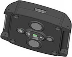
This article is written about Analog Devices’ latest wearable VSM platform and the sensor technologies used (wearable device shown in Figure 1). ADI is not a manufacturer of final products. However, this platform has been designed as a reference to help the electronic designer and system architect to speed up their development process while designing new, smarter, and more accurate wearable devices for the professional and medical market.
What Are We Measuring? How and Where?
A broad range of vital parameters can be measured with a wearable device. Depending on the overall objective, certain parameters are more important to measure than others. The location of the wearable device on the body has a big impact on what can be measured and what cannot. The most obvious location is the wrist. We are accustomed to wearing a device on our wrist, which is the reason why so many products like smart-watches and wrist-worn devices are on the market. Besides measuring on the wrist, the head is another good location for wearables. For example, headphones and earbuds are offered in different styles that contain embedded sensors to measure parameters such as heart-rate, oxygen saturation, and temperature. The third location for wearables on the body is the chest. First generation heart-rate monitors have been designed around a chest strap and this biopotential measurement method is still a very accurate technique. Today we tend to prefer a chest patch, though, as the strap is not very comfortable to wear. Several manufacturers are involved in the design of smart patches to monitor vital parameters.
Figure 1. ADI’s GEN II integrated wearable device reference design.
Depending on body location, we are not just faced with the choice of which parameters can be measured, but also with what technology should be used. For heart rate measurement, for instance, biopotential measurement is one of the oldest technologies. Signals are strong and easy to retrieve from the body by utilizing two or more electrodes. For this approach, integration of the circuitry in a chest strap or headphones is perfect. However, measuring biopotential signals at a single point like the wrist is nearly impossible. You need to measure across the heart, where these electric signals are being generated. For single spot measurement, optical technology is more appropriate. Light is sent into the tissue and its reflection, as a result of blood-flow in the arteries, is captured and measured. From this optically received signal, beat-to-beat information can be retrieved. This technology sounds rather straightforward—however, there are several challenges and influencers that can make the design really difficult, such as motion and ambient light.
Analog Devices GEN II wearable device reference platform has most of the previously described technologies on board. The device is designed to be worn on the wrist. However, you can also remove the soft belt and attach the device to the chest to use it as a smart patch. The device includes technology to support biopotential measurement, optical heart-rate measurement, bioimpedance measurement, motion tracking, and temperature measurement—all integrated in a tiny, battery-operated device.
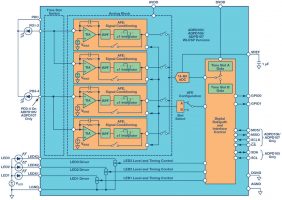
Figure 2. Block diagram of ADPD105/ADPD106/ADPD107.
The Underlying Message
Why did Analog Devices design a system like the GEN II wearable device? The goal for a system like this is to be able to evaluate various sensing technologies and to measure, in an easy way, several vital parameters on the body. These measurements can be stored into flash memory or sent over a BLE wireless connection to a smart device. Since the measurements are done simultaneously, it also can help to find correlation among several parameters. Biomedical engineers, algorithm providers, and entrepreneurs continuously are looking for new technologies, applications, and use cases to detect diseases at an earlier stage, in order to minimize negative effects or damage to the body that might occur at a later stage.
Sensors Are Making the Device
The device is designed around two PCBs, which are stacked as a sandwich. The main board contains a low power processor, a BLE radio, and the complete power management section including battery conditioning and charging. A second board supports all sensing technologies.
The optical system for PPG measurement (photoplethysmogram) is built around the ADPD107, ADI’s second generation optical analog front end. The block diagram of the ADPD family is shown in Figure 2.
The ADPD107 operates as a complete transceiver, driving the LEDs in the system and measuring the return signal from the photodiode(s). The objective is to measure photocurrent that is as high as possible, for a given amount of LED current spent (current transfer ratio). The input receive signal chain is designed around a configurable transimpedance amplifier, where the gain can be programmed in four steps up to 200k. The second stage is responsible for ambient light rejection. Ambient light interferers are a big issue, especially when the light is modulated, like with solid-state lighting systems with LEDs or energy saving lamps. The ambient light rejection block contains a band-pass filter followed by an integrator to support synchronous demodulation. This is a key function and rejects external light interferers very effectively. When, for whatever reason, the ambient light rejection stage is not needed, this block can be bypassed completely.
The optical system is makes use of light pulses. There are three LED current sources, which are fully programmable. The maximum LED currents are programmable and can be as high as 370 mA. Also, the pulse width is programmable and can be as narrow as 1 μs. However, for a good signal response, pulse width should be around 2 μs to 3 μs. Usually a series of LED pulses are given while the analog-to-digital converter is sampling the photodiode receive signals related to the pulsed LED transmit pulses. The digital engine is able to average multiple samples to increase the overall effective number of bits.
Along with the optical system, mechanical design also has a major impact on overall performance. In this GEN II device, the optical components have been selected as discrete devices. This gives a lot of flexibility on the photodiode selections and the LED wavelengths, as well as mechanical constraints such as spacing between LEDs and photodiodes. The GEN II device supports two green LEDs, one red LED, and one infrared LED. For those who don’t have a lot of experience in designing optical systems, it might be easier to integrate a complete optical module.
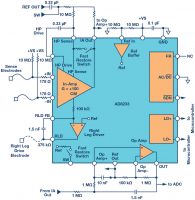
Figure 3. Block diagram of the AD8233 ECG front end.
There are different flavors in terms of the number of photodiodes, their sizes, and the selection of LED wavelengths. The latest modules have been developed in such a way that they show a great optical performance even when they are mounted behind a plastic window. The first generation required a split window to reject internal light pollution, which can be seen as optical crosstalk. A split window helped to reduce dc offsets from light, coming directly from the LEDs without penetration into the body. Such a split window is not easy to integrate, nor is it attractive from a cost point of view. The latest families, such as the ADPD144RIZ and ADPD175GGIZ, have been improved substantially and even with just one complete window the ILP effects have been reduced to almost zero.
Biopotential measurement is supported by two individual AD8233 analog front ends. The AD8233 (see Figure 3) is ADI’s second generation single-lead ECG front end with embedded right leg drive (RLD) capability and has been designed to extract, amplify, and filter small biopotential signals in the presence of noisy environments. Focus applications for this component are wearable devices, portable home care systems, and exercise equipment. The AD8233 operates in a dc coupled configuration. The input stage is divided over 2 gain stages. The first stage, with limited gain, is followed by a second-order, high-pass filter and a second gain stage. The total gain of this input block is 100 V/V, which includes the subtraction of the offset as a result of the electrode half-cell potential. The second stage in the AD8233 is combined with a third-order, low-pass filter. It is second-order Sallen Key working in unity followed by an additional low-pass filter. The objective of this filter is to reject all EMG related signals coming from muscle activity.
The operating frequency of the biopotential front end depends on the use case. For a normal heart rate monitor, where just QRS detection is needed, the operating frequency range is much less compared to an ECG monitor where more information is required, such as timing and amplitude data from the P-wave vs. QRS-Complex vs. T-wave. The band of interest for the AD8233 can be configured by external resistors and capacitors. To support flexibility, the GEN II wearable device has the ECG front end connected to the embedded electrodes, configured in a sports bandwidth, supporting a band of interest from 7 Hz to 25 Hz. The second AD8233 that can be operated in combination with external electrodes is configured to monitor signals from 0.5 Hz up to 40 Hz. In principle, nearly any bandwidth can be selected. However, this requires modifications of the hardware by changing R and C settings.
Depending on the required accuracy, the AD8233 output can be sent to the 12-bit successive approximation register (SAR) ADC embedded in the Cortex®-M3 processor on the sensor board, or digitization can be done by the standalone 16-bit, AD7689 SAR ADC. Trade-offs can be made and depend on either accuracy or battery lifetime.
At the back-side of the device you’ll find two electrodes. These have a double function. In addition to ECG measurement, these also can be used for electrodermal activity (EDA).
EDA, or galvanic skin response (GSR), is related to the conductivity of the skin, which is momentarily changed by emotion, coming from either an internal or external stimuli—skin impedance changes, for instance, as a result of stress or epilepsy. The GEN II device is able to detect this minute change in conductivity. The system is making use of an ac excitation signal, which is applied over the two dry electrodes. Wet electrodes can be used as well and will be better. However, this device is just making use of two embedded dry stainless steel electrodes. The main advantage of using an ac excitation signal is that this will not polarize the electrodes. The receive signal chain represents a transimpedance amplifier, followed by the AD7689 16-bit, SAR ADC. The ADC sampling rate is higher much higher than the excitation rate, for performance reasons. The ADC output is followed by a discrete Fourier transform (DFT) engine, running on the ADuCM3029 processor, to represent the complex impedance. The measurement principle as described above is capable for measuring skin impedance or skin conductance at a high signal-to-noise ratio and a very good suppression of 50 Hz/60 Hz environmental noise. The circuit around this measurement principle is completely built with discrete components. The main reason for this design decision is flexibility and accuracy at rather low power dissipation. In the meantime, ADI is working on a new chip supporting the application as described above. It delivers a high level of accuracy at minimum power dissipation. The ADuCM350 supports comparable measurements as well, although this chip is not optimized for power sensitive applications.
A wearable device is worthless for measuring vital parameters without having a notion of what the human body is doing. For that reason, motion detection and profiling are important. Some use cases like optical heart rate monitoring are very sensitive to motion and motion can destroy the accuracy of the measurement completely. For that reason, motion also needs to be tracked to compensate for artifacts. Motion sensors will help to track movement and, where needed, motion can be compensated in the final outcome of the readings. The ADXL362 is the lowest power motion sensor available. It has a 3-axis MEMS sensor with an integrated 12-bit ADC to detect motion in the X-, Y-, and Z-axis. The output data rate (ODR) of the ADC represents the power dissipation of the sensor—which is 3 μA at the full ODR of 400 Hz per axis. In Figure 4, a plot of the power dissipation as a function of the output data rate is shown.
Figure 4. ADXL362 power consumption as a function of the output data rate.
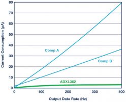
This sensor can also be used as a motion activation switch. There is a possibility to reduce the sampling rate to just 6 Hz. Every 150 ms, the sensor wakes up and measures the motion activity. Without motion, it goes straight back to sleep for another 150 ms. At the moment, motion is being detected at a g force equal or higher than the preprogrammed threshold level and for at least the minimum time programmed, the sensor generates an interrupt or enables a power switch to turn on the application. With this mode, the sensor is consuming only 300 nA, and can run for years from a single coin cell battery. All the use cases summarized make the motion sensor a must have in a wearable device
Temperature sensing is another vital parameter. That is why the GEN II wearable has two temperature sensors embedded. The wrist-worn device uses NTCs to measure both skin temperature and the temperature inside the device—there are multiple methods to measure temperature via sensors contacting the body. The NTCs are powered and conditioned by discrete circuitry and the 16-bit ADC finally converts the signals into the digital domain. ADI has a wide range of temperature sensors, in various accuracy levels. The reason that the GEN II temperature sensors have been built discrete is that several function like the ADC were available anyway, so the designers reused several blocks as much as possible to reduce redundancy and save additional power.
ADuCM3029, Where Everything Comes Together
The GEN II device makes use of two processors. It is not that this is absolutely needed, but rather to provide more flexibility. The interface board with BLE radio has one processor and the same device is used on the sensor board to be able to run autonomously.
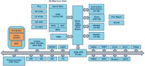
The ultra low power ADuCM3029 has been integrated to collect the sensor data and to run the algorithms. Figure 5 gives an overview of the integrated blocks in the processor.
The core is a 26 MHz Cortex-M3 with a rich peripheral set, on-board memory, and an analog front-end. There are 4 operating modes, where in full operation the chips consumes 38 μA per MHz. In case processing power is not needed, the device can run in flexi-mode. In this operating mode, the analog front end is running, peripherals are active, and the measured signals can be stored in memory through DMA. This mode consumes 300 μA only and so makes the chip very attractive for low power, battery-operated systems. There are several security features embedded for code protection and a hardware accelerator for cryptographic functions.
Figure 5. Integrated ADuCM3029 blocks.
Selection of the Use Cases
The GEN II wearable device can be used for many purposes. The sensors can be integrated in smart watches, but the range of functions, including accurate heart rate monitoring and activity measurement/calorie burn, are also helpful for sport watches. The trade-off between a smart watch and sport watch is mainly made between accuracy vs. battery lifetime.
The device can used to measure stress or emotional state. Usually a combination of measurements is used to get a reliable reading, such as skin impedance together with heart rate variability and temperature.
Blood pressure monitoring is another interesting use case. This is a very important parameter, but most of the systems are cuff-based, which is hard to integrate in a wearable and continuous system. There are certain techniques that can be used to measure blood pressure without the need for a cuff. One technology is by making use of the pulse-wave transmit time (PTT). This requires ECG measurement in combination with PPG measurement. The sensors inside the GEN II wearable device can support this.
The last key market is related to elderly care and independent living. There is huge need for systems that can help caregivers monitor certain parameters remotely. This wearable device supports 95% of the features needed. The system monitors several vital parameters. It can track if people are moving or walking, but is also able to detect falls. The missing piece in the wearable design is an emergency button, but this is a matter of connecting one I/O pin on the processor to a switch on top of the device.
From Prototype to Product
The GEN II device has many high performance sensors and features embedded in a small wearable system. Besides the electronic design, many mechanical aspects have also been taken into consideration. This makes the platform very attractive to design companies and device manufacturers that are focusing on the semi-professional sports market, the medical market, and companies involved in systems for smart buildings, independent living, or elderly care. All parameters can be measured simultaneously, but algorithms need to complement the application to support the use cases. Instead of building hardware before testing and validating the algorithms, this device will give developers and device manufacturers a quick start. The GEN II device is available in limited quantities and ADI is very interested in working with design companies and algorithm providers to develop a state-of-the-art system that can be sold to the professional caregivers and health insurance companies.
More information can be found at analog.com/healthcare.
Jan-Hein Broeder – Healthcare Business Development Manager, Analog Devices, Inc.
About the Author
Jan-Hein Broeders is healthcare business development manager for Analog Devices’ Healthcare Business in EMEA. He works very closely with the healthcare industry to translate its present and future requirements into solutions, based on Analog Devices market-leading linear and data converter technology, as well as products for digital signal processing and power. Jan-Hein started in the semiconductor industry 20 years ago as an analog field application engineer at Burr-Brown. Five years after the acquisition by Texas Instruments, he joined ADI as global FAE for Philips. He has been in his current healthcare role since 2008. He holds a bachelor’s degree in electrical engineering from the University of ’s-Hertogenbosch, the Netherlands. He can be reached at jan.broeders@analog.com.


